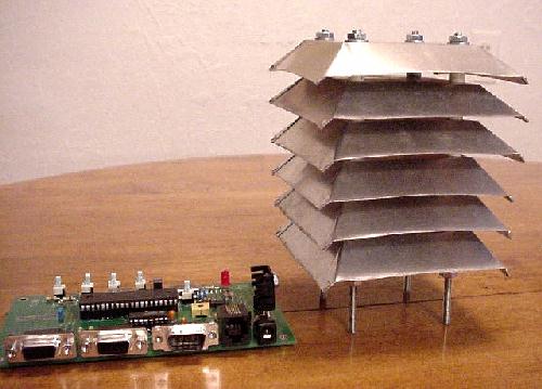
Figure 1: An assembled Radiation Shield
This page describes Russ's project to make his own heat shield for a stand-alone temperture sensor that is ventillated. May putting the new DS18S20 sensor in Russ's shield, you should be as accurate as you can get.
Software releases after 1.09.0 will notice the fact you have two sensors installed and will ask you the ID of the one you want to use. This way you don't have to remove the old one to get support for the new one.
A problem with the 1-Wire Weather Station is that the temperature sensor is inside the sealed plastic housing. When the weather station is in the direct sun, the temperature sensor can read high by up to 20 degrees F. Fortunately, there is a inexpensive way to reduce this error greatly. That is to build a homebrew ventilated radiation shield to house the temperature (and humidity) sensors in a different enclosure than the wind part of the weather station. Temperature (and humidity) sensors need to be closely coupled to the air rather than inside a sealed unit. The radiation shield will accomplish this, and also will provide protection for the sensors from rain, snow, hail and sun.
Figure 1 shows a picture of the assembled radiation shield. The basic idea is that the sun shines on the top layer and heats it up, causing some reradiation to the next lower shield, but some of the heat is carried away by cross wind. At each layer some of the heat is carried away by the wind, reducing the amount of heat reradiated toward the sensor. If the wind is four mph or greater, the temperature error will about 2 deg F or less, even in the direct sun.
The materials used in the construction of the radiation shield are available in most hardware stores or lumber yards. The shielding material is aluminum roof flashing. It comes in rolls that are about 14.25" wide. A square 14.25" on a side will provide material for nine of the individual shielding elements shown in Fig. 1 and only six are needed. Assume that you will make a few not-so-good ones before you make the good ones that you will use in the final shield. Scribe the square sheet into a set of 3 by 3 squares, with each square being one third of the width of the roof flashing. It is important that these squares have equal sides and right angle corners. Use a carpenter's square to measure and mark.
Next, scribe diagonals both directions through all of the squares. Then scribe lines that are 1 inch away from the sides of the boxes in both directions in all squares . These are the lines where the bending will occur. It is faster to do the marking by doing three squares at once. These last lines intersect the diagonals 1.414" in from the corners of the squares. At this point, you should have 9 squares marked. Each square should have 2 diagonal lines intersecting in the center of the square. Each square should also have 4 lines parallel to the sides, 1" away from the sides.
Next, cut each of the squares out. It is better to use shears that are non-serrated. If you use serrated shears, then lightly hammer the edges on smooth metal to pound out the serrated edge. The reason that a serrated edge is undesirable is that it gives the water more surface to hang on to. You want the water to drip off as much as possible. Water that hangs on to the edges and then freezes or evaporates involves latent heat which can affect the temperature measurement.
With the nine individual squares, cut from each corner in toward the center on the diagonal lines until you get to the two lines that are parallel to the sides. These cuts should be 1.414" long. Then, bend up one side 45 degrees between the diagonal line cuts, making the bend on the scribed line parallel to the side. Then do the same thing to the opposite side, again making the bend 45 degrees. Next, bend the third side up until it touches the other two side, again making the bend on the scribed line. Now, fold the third side around the first two sides to form a corner of the downward sloping surface. Using a pair of pliers or other tool to make this fold will result in the tips of the two sides protruding beyond the other side so they can act as tabs to be bent back and secure the corner. Figure 2 shows a close-up picture of one of the corners and how the turned-down corners are shaped.
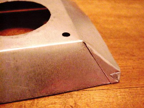
After you have built six good aluminum shields, cut a 2 5/8" square out of 1/8" rigid plastic (exact thickness is not important). This piece of plastic will be used as a form to mark the mounting holes in the aluminum shields and then will be installed as a support below the top shield. The purpose of the plastic is to provide some insulation below the hottest layer and to act as a support for the top layer in the event of a hail storm. Mark diagonals in the square piece of plastic and mark four holes near the corners on the diagonals about 3/8" from the edges. Drill the 4 holes in the plastic for a #8 screw. Then using the plastic as a form, mark each of the 6 aluminum shields for four mounting holes. Drill these holes for #8 screw. Figure 2 shows the location of one of these holes.
Using rigid white plastic tube suitable for #8 threaded rod, cut 16 sections 5/8" long. A metal hack saw works well for this. Next cut 4 sections that are 5/8" less the thickness of the plastic support used to mark holes. Also, cut 4 sections that are 7/8" long. Cut 4 pieces of #8 threaded rod 6" long and put screws on one end of each.
Then assemble by putting the 4 pieces of threaded rod through the top aluminium shield with the screws and washers on top. Next put the threaded rods throught the plastic square and then put the 4 short white plastic pieces on the threaded rods and then another aluminium shield. Repeat the process until all 6 aluminum shields are on the threaded rods, and then install the long pieces of white plastic tube. Finally, put screws and washers on the threaded rods and tighten.
Inspect the overall structure and see if it would look better if you rearranged any of the aluminum shields. If so, rearrange the shields to determine which two will be on the bottom of the structure. With these two, you need to cut a opening in the center. I used a 1 7/8" hole in the center. It is difficult to drill a hole this large and so I drilled a smaller hole and used a nibbler to enlarge it to the desired size. The shape of the opening is not too important. However, it should be large enough to let air pass freely through. Figure 2 shows this opening.
Spray paint the outside of the shield with the whitest exterior paint that you can find. Then, using the 4 ends of the threaded rod, arrange some mounting arrangement and some way of holding the temperature sensor in the center of the opening in the bottom two shield layers with the sensor toward the top of this opening.